- binsUserobjects providing a spatial bin given a point
C++ Type:std::vector<UserObjectName>
Controllable:No
Description:Userobjects providing a spatial bin given a point
- fieldField to apply this object to
C++ Type:MooseEnum
Controllable:No
Description:Field to apply this object to
- gap_thicknessthickness of gap region for which to accept contributions to the side integral over the gap, expressed in the same units as the mesh.
C++ Type:double
Unit:(no unit assumed)
Range:gap_thickness > 0.0
Controllable:No
Description:thickness of gap region for which to accept contributions to the side integral over the gap, expressed in the same units as the mesh.
NekBinnedPlaneIntegral
Compute the spatially-binned side integral of a field over the NekRS mesh
Description
This user objects performs a side integral of a specified field over face "bins" defined on the NekRS mesh. For illustration, consider a rectangular face aligned with the axis on , , and . Because this face may not necessarily align with the faces of NekRS's mesh elements, a 2-D face integral is approximated as a volume integral over a prism with a face-normal thickness of gap_thickness, denoted here as :
(1)
where is the value of the user object and is the specified field. To be clear, this user object is not evaluated on the NekRSMesh mesh mirror, but instead on the mesh actually used for computation in NekRS.
warningwarning
This user object can produce very inaccurate results due to the nature of the averaging performed in Eq. (1). The averaging in Eq. (1) is essentially the same as applying a delta function that is unity at nodes within a small distance of the face, and zero for all other nodes. However, this implementation is technically no different from a different selection of which does not change the number of GLL points "hit". For illustration, consider the setup shown in Figure 1. While Eq. (1) shows that the normalization to an area is obtained by dividing by an integral, in implementation we do not have a means to directly compute this integral in the denominator. Instead, we divide the numerator in Eq. (1) by the gap_thickness.
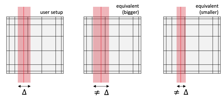
Figure 1: Illustration of potential inaccuracies with this object; black lines show the connections between GLL points and the shaded red areas show the contributing volumes to a face
However, if the effective integrating volume does not "hit" GLL points that are away from the gap, then the effective thickness of the integral is technically indistinguishable from other values of that hit the same number of GLL points. Because the mesh may be unstructured and not be oriented in any convenient way with respect to the faces (unlike the structured depiction in Figure 1), there is no other value of gap_thickness by which we could divide Eq. (1) to correctly obtain areas.
Therefore, we recommend only using this class if you know that your mesh is structured and you have selected a gap_thickness such that for every bin, your GLL points would exactly lie on the surface of a rectangular prism of width . Instead, you should use the NekBinnedPlaneAverage object to get an average over the face, and then multiply that value by the known area of the gap (i.e. don't use this object to try to calculate the gap area).
The field is specified with the field parameter, which may be one of:
pressure: pressuretemperature: temperature, a.k.a. zeroth passive scalarvelocity: magnitude of velocityvelocity_x: -component of velocityvelocity_y: -component of velocityvelocity_z: -component of velocityvelocity_x_squared: -component of velocity, squaredvelocity_y_squared: -component of velocity, squaredvelocity_z_squared: -component of velocity, squaredvelocity_component: velocity vector dotted against another vectorscalar01: first passive scalarscalar02: second passive scalarscalar03: third passive scalarunity: the value 1.0
Setting field = unity is equivalent to computing the surface area.
When using field = velocity_component, the manner in which the velocity direction is selected is given by the velocity_component parameter, which may be one of:
normal: normal to the face bins (only valid for the side binning user objects)user: arbitrary user-specified direction, provided with thevelocity_directionparameter
When using a velocity component as the field, this user object computes the dot product of the velocity with the specified direction. To retain the components of the dot product, such as for visualizing vector glyphs of the user object result in Paraview, you can use a NekSpatialBinComponentAux.
If running NekRS in non-dimensional form (and you have indicated the appropriate nondimensional scales with the Dimensionalize sub-block for the [Problem]) then the value of this object is shown in dimensional units.
The bins (which can be a combination of side and volume bins) are specified by providing a list of binning user objects with the bin parameter. This user object requires providing one and only one "side" bin, which defines the planes over which to integrate. The available user objects for specifying side spatial bins are:
The side bins can then be combined with any number of "volume" bins to further subdivide the domain. Available user objects for specifying the volume spatial bins are:
If more than one bin is provided, then the bins are taken as the product of each individual bin distribution.
It is recommended to set map_space_by_qp = true for this user object; otherwise, all the GLL points in an element with centroid closer than to the gap plane will contribute to the plane integral.
schooltip
You can visualize this user object (i.e., the bin integrals) using a SpatialUserObjectAux.
Example Input Syntax
As an example, the input below defines side bins as the gap planes in a hexagonal lattice of pins (named subchannel_binning). These side bins are then combined with a LayeredBin to perform integrals over the gap planes in num_layers axial segments.
[UserObjects<<<{"href": "../../syntax/UserObjects/index.html"}>>>]
  [subchannel_binning]
    type = HexagonalSubchannelGapBin<<<{"description": "Creates a unique spatial bin for each subchannel in a hexagonal lattice", "href": "HexagonalSubchannelGapBin.html"}>>>
    bundle_pitch<<<{"description": "Bundle pitch, or flat-to-flat distance across bundle"}>>> = 0.02583914354890463
    pin_pitch<<<{"description": "Pin pitch, or distance between pin centers"}>>> = 0.0089656996
    pin_diameter<<<{"description": "Pin outer diameter"}>>> = 7.646e-3
    n_rings<<<{"description": "Number of pin rings, including the centermost pin as a 'ring'"}>>> = 2
  []
  [axial_binning]
    type = LayeredBin<<<{"description": "Creates a unique spatial bin for layers in a specified direction", "href": "LayeredBin.html"}>>>
    direction<<<{"description": "The direction of the layers (x, y, or z)"}>>> = z
    num_layers<<<{"description": "The number of layers between the bounding box of the domain"}>>> = 6
  []
  [gap_avg]
    type = NekBinnedPlaneAverage<<<{"description": "Compute the spatially-binned side average of a field over the NekRS mesh", "href": "NekBinnedPlaneAverage.html"}>>>
    bins<<<{"description": "Userobjects providing a spatial bin given a point"}>>> = 'subchannel_binning axial_binning'
    field<<<{"description": "Field to apply this object to"}>>> = temperature
    gap_thickness<<<{"description": "thickness of gap region for which to accept contributions to the side integral over the gap, expressed in the same units as the mesh."}>>> = ${gap_thickness}
    map_space_by_qp<<<{"description": "Whether to map the NekRS spatial domain to a bin according to the element centroids (true) or quadrature point locations (false)."}>>> = true
  []
  [gap_area]
    type = NekBinnedPlaneIntegral<<<{"description": "Compute the spatially-binned side integral of a field over the NekRS mesh", "href": "NekBinnedPlaneIntegral.html"}>>>
    bins<<<{"description": "Userobjects providing a spatial bin given a point"}>>> = 'subchannel_binning axial_binning'
    field<<<{"description": "Field to apply this object to"}>>> = unity
    gap_thickness<<<{"description": "thickness of gap region for which to accept contributions to the side integral over the gap, expressed in the same units as the mesh."}>>> = ${gap_thickness}
    map_space_by_qp<<<{"description": "Whether to map the NekRS spatial domain to a bin according to the element centroids (true) or quadrature point locations (false)."}>>> = true
  []
[]The result of the user object can then be visualized with a SpatialUserObjectAux.
Input Parameters
- check_zero_contributionsTrueWhether to throw an error if no GLL points/element centroids in the NekRS mesh map to a spatial bin; this can be used to ensure that the bins are sufficiently big to get at least one contributing point from the NekRS mesh.
Default:True
C++ Type:bool
Controllable:No
Description:Whether to throw an error if no GLL points/element centroids in the NekRS mesh map to a spatial bin; this can be used to ensure that the bins are sufficiently big to get at least one contributing point from the NekRS mesh.
- interval1Frequency (in number of time steps) with which to execute this user object; user objects can be expensive and not necessary to evaluate on every single time step. NOTE: you probably want to match with 'time_step_interval' in the Output
Default:1
C++ Type:unsigned int
Controllable:No
Description:Frequency (in number of time steps) with which to execute this user object; user objects can be expensive and not necessary to evaluate on every single time step. NOTE: you probably want to match with 'time_step_interval' in the Output
- map_space_by_qpFalseWhether to map the NekRS spatial domain to a bin according to the element centroids (true) or quadrature point locations (false).
Default:False
C++ Type:bool
Controllable:No
Description:Whether to map the NekRS spatial domain to a bin according to the element centroids (true) or quadrature point locations (false).
- velocity_componentuserDirection in which to evaluate velocity when 'field = velocity_component.' Options: user (you then need to specify a direction with 'velocity_direction'); normal
Default:user
C++ Type:MooseEnum
Controllable:No
Description:Direction in which to evaluate velocity when 'field = velocity_component.' Options: user (you then need to specify a direction with 'velocity_direction'); normal
- velocity_directionUnit vector to dot with velocity, for 'field = velocity_component'. For example, velocity_direction = '1 1 0' will get the velocity dotted with (1/sqrt(2), 1/sqrt(2), 0).
C++ Type:libMesh::Point
Controllable:No
Description:Unit vector to dot with velocity, for 'field = velocity_component'. For example, velocity_direction = '1 1 0' will get the velocity dotted with (1/sqrt(2), 1/sqrt(2), 0).
Optional Parameters
- allow_duplicate_execution_on_initialFalseIn the case where this UserObject is depended upon by an initial condition, allow it to be executed twice during the initial setup (once before the IC and again after mesh adaptivity (if applicable).
Default:False
C++ Type:bool
Controllable:No
Description:In the case where this UserObject is depended upon by an initial condition, allow it to be executed twice during the initial setup (once before the IC and again after mesh adaptivity (if applicable).
- execute_onTIMESTEP_ENDThe list of flag(s) indicating when this object should be executed. For a description of each flag, see https://mooseframework.inl.gov/source/interfaces/SetupInterface.html.
Default:TIMESTEP_END
C++ Type:ExecFlagEnum
Controllable:No
Description:The list of flag(s) indicating when this object should be executed. For a description of each flag, see https://mooseframework.inl.gov/source/interfaces/SetupInterface.html.
- execution_order_group0Execution order groups are executed in increasing order (e.g., the lowest number is executed first). Note that negative group numbers may be used to execute groups before the default (0) group. Please refer to the user object documentation for ordering of user object execution within a group.
Default:0
C++ Type:int
Controllable:No
Description:Execution order groups are executed in increasing order (e.g., the lowest number is executed first). Note that negative group numbers may be used to execute groups before the default (0) group. Please refer to the user object documentation for ordering of user object execution within a group.
- force_postauxFalseForces the UserObject to be executed in POSTAUX
Default:False
C++ Type:bool
Controllable:No
Description:Forces the UserObject to be executed in POSTAUX
- force_preauxFalseForces the UserObject to be executed in PREAUX
Default:False
C++ Type:bool
Controllable:No
Description:Forces the UserObject to be executed in PREAUX
- force_preicFalseForces the UserObject to be executed in PREIC during initial setup
Default:False
C++ Type:bool
Controllable:No
Description:Forces the UserObject to be executed in PREIC during initial setup
Execution Scheduling Parameters
- control_tagsAdds user-defined labels for accessing object parameters via control logic.
C++ Type:std::vector<std::string>
Controllable:No
Description:Adds user-defined labels for accessing object parameters via control logic.
- enableTrueSet the enabled status of the MooseObject.
Default:True
C++ Type:bool
Controllable:Yes
Description:Set the enabled status of the MooseObject.
- use_displaced_meshFalseWhether or not this object should use the displaced mesh for computation. Note that in the case this is true but no displacements are provided in the Mesh block the undisplaced mesh will still be used.
Default:False
C++ Type:bool
Controllable:No
Description:Whether or not this object should use the displaced mesh for computation. Note that in the case this is true but no displacements are provided in the Mesh block the undisplaced mesh will still be used.
Advanced Parameters
- prop_getter_suffixAn optional suffix parameter that can be appended to any attempt to retrieve/get material properties. The suffix will be prepended with a '_' character.
C++ Type:MaterialPropertyName
Unit:(no unit assumed)
Controllable:No
Description:An optional suffix parameter that can be appended to any attempt to retrieve/get material properties. The suffix will be prepended with a '_' character.
- use_interpolated_stateFalseFor the old and older state use projected material properties interpolated at the quadrature points. To set up projection use the ProjectedStatefulMaterialStorageAction.
Default:False
C++ Type:bool
Controllable:No
Description:For the old and older state use projected material properties interpolated at the quadrature points. To set up projection use the ProjectedStatefulMaterialStorageAction.