Step 2: Conjugate Heat Transfer
Complete input file for this step: 02_core.i
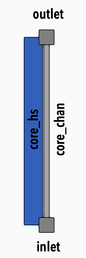
Figure 1: Model diagram
In this step, we will add a heating block to our flow channel, set up heat source, and connect the solid block to the flow channel via conjugate heat transfer.
Parameters of the Heated Channel
We include the core parameters as named parameters to the top of the input file so they can be used in the components:
core_length = 1. # m
core_n_elems = 25
core_dia = '${units 2. cm -> m}'
core_pitch = '${units 8.7 cm -> m}'
A_core = '${fparse core_pitch^2 - 0.25 *pi * core_dia^2}'
P_wet_core = '${fparse 4*core_pitch + pi * core_dia}'
Dh_core = '${fparse 4 * A_core / P_wet_core}'
For total power used for heating the block, we prescribe a parameter called tot_power.
tot_power = 2000 # W
Solid Properties
To set up a heat conduction, we will need to define a solid material used in the block with heat conduction. To do that, we put the following block into a top-level SolidProperties block:
[SolidProperties<<<{"href": "../../../../syntax/Modules/SolidProperties/index.html"}>>>]
  [steel]
    type = ThermalFunctionSolidProperties<<<{"description": "Function-based thermal properties.", "href": "../../../../source/solidproperties/ThermalFunctionSolidProperties.html"}>>>
    rho<<<{"description": "Density"}>>> = 8050
    k<<<{"description": "Thermal conductivity"}>>> = 45
    cp<<<{"description": "Isobaric specific heat"}>>> = 466
  []
[]
where rho, k, and cp are density, thermal conductivity, and specific heat, respectively. The name steel is arbitrary and is used to refer to this material from other parts of the input file.
Heat Structure
A heat structure is a 2D or 3D component that is used for modeling heat conduction. In our setup, the heating block is a rod, so we use HeatStructureCylindrical for the model. The component takes the position parameter, which is the location in 3D space. The orientation parameter is the axial directional vector, length is the axial length, and n_elems is the number of elements in the axial direction.
The number of axial elements must match the number of elements in the flow channel.
In radial direction we define one block called block and assign our previously defined steel material to it. The number of radial element in this block will be 3.
[Components<<<{"href": "../../../../syntax/Components/index.html"}>>>]
  [core_hs]
    type = HeatStructureCylindrical<<<{"description": "Cylindrical heat structure", "href": "../../../../source/components/HeatStructureCylindrical.html"}>>>
    position<<<{"description": "Start position of axis in 3-D space [m]"}>>> = '0 0 0'
    orientation<<<{"description": "Direction of axis from start position to end position (no need to normalize)"}>>> = '0 0 1'
    length<<<{"description": "Length of each axial section [m]"}>>> = ${core_length}
    n_elems<<<{"description": "Number of elements in each axial section"}>>> = ${core_n_elems}
    names<<<{"description": "Name of each radial region"}>>> = 'block'
    widths<<<{"description": "Width of each radial region [m]"}>>> = '${fparse core_dia / 2.}'
    solid_properties<<<{"description": "Solid properties object name for each radial region"}>>> = 'steel'
    solid_properties_T_ref<<<{"description": "Density reference temperatures for each radial region. This is required if 'solid_properties' is provided. The density in each region will be a constant value computed by evaluating the density function at the reference temperature."}>>> = '300'
    n_part_elems<<<{"description": "Number of elements of each radial region"}>>> = 3
  []
[]
Heat Source
Our heating will be given by the specified total power parameter. For this, we need to include TotalPower component and link it with another component – HeatSourceFromTotalPower.
[Components<<<{"href": "../../../../syntax/Components/index.html"}>>>]
  [total_power]
    type = TotalPower<<<{"description": "Prescribes total power via a user supplied value", "href": "../../../../source/components/TotalPower.html"}>>>
    power<<<{"description": "Total power [W]"}>>> = ${tot_power}
  []
[]
[Components<<<{"href": "../../../../syntax/Components/index.html"}>>>]
[core_heating]
type = HeatSourceFromTotalPower<<<{"description": "Heat generation from total power", "href": "../../../../source/components/HeatSourceFromTotalPower.html"}>>>
hs<<<{"description": "Heat structure in which to apply heat source"}>>> = core_hs
regions<<<{"description": "Heat structure regions where heat generation is to be applied"}>>> = block
power<<<{"description": "Component that provides total power"}>>> = total_power
[]
[]HeatSourceFromTotalPower needs to know which heat structure and which part it acts on, which is done via the hs and regions parameters. The link to the TotalPower component is created via power parameter which takes the name of the TotalPower component.
Heat Transfer
To exchange heat between a flow channel and heat structure, we use the HeatTransferFromHeatStructure1Phase component. We need to specify the flow_channel parameter which takes the name of the connected flow channel, hs parameter which is the name of the heat structure component, hs_side parameter which is the side of the heat structure and can be either inner or outer.
Lastly, we need to specify P_hf, which is the heated perimeter. The heat transfer coefficient Hw is calculated by the closure set.
[Components<<<{"href": "../../../../syntax/Components/index.html"}>>>]
  [core_ht]
    type = HeatTransferFromHeatStructure1Phase<<<{"description": "Connects a 1-phase flow channel and a heat structure", "href": "../../../../source/components/HeatTransferFromHeatStructure1Phase.html"}>>>
    flow_channel<<<{"description": "Name of flow channel component to connect to"}>>> = core_chan
    hs<<<{"description": "Heat structure name"}>>> = core_hs
    hs_side<<<{"description": "Heat structure side"}>>> = outer
    P_hf<<<{"description": "Heat flux perimeter [m]"}>>> = '${fparse pi * core_dia}'
  []
[]
This concludes the step of coupling a flow channel with a heat structure.