- inputThe mesh we want to modify
C++ Type:MeshGeneratorName
Controllable:No
Description:The mesh we want to modify
NekMeshGenerator
Converts MOOSE meshes to element types needed for Nek (Quad8 or Hex20), while optionally preserving curved edges (which were faceted) in the original mesh.
Description
This mesh generator is used to convert:
A HEX27 mesh into a HEX20 mesh, or
A QUAD9 mesh into a QUAD8 mesh
These two element types (HEX20, QUAD8) are compatible with NekRS's exo2nek utility that generates a NekRS mesh (the custom .re2 format). This page is written for the HEX27 to HEX20 conversion, but the QUAD9 to QUAD8 conversion features are identical, just executed in 2-D. This mesh generator will:
Take a HEX27 mesh and convert it into an equivalent HEX20 mesh
Optionally move nodes to be conformal with a cylinder. You can also optionally move nodes at polygon corners to a cylindrical radius of curvature. This allows NekRS to exactly represent curved corners of meshes that represent regular polygons, such as for curving the corners of a mesh representing a six-sided duct. Set
geometry_type = cylinderfor either of these.Optionally move nodes to be conformal with a sphere surface.
NekRS uses a high-order spectral element solution, which will exactly represent circular surfaces (e.g. circles, cylinders, spheres) its GLL points (as long as the HEX20 elements have their mid-side nodes one the curve, which is what this mesh generator does for you).
commentnote:"Have a HEX8 mesh instead of a HEX27 mesh?
If you have a HEX8 mesh, you can convert it to a HEX27 mesh by adding second_order = true in a separate MOOSE file that generates your mesh (which can be as simple as just reading the mesh from a file with a FileMeshGenerator, like this
[Mesh]
  [file]
    type = FileMeshGenerator
    file = mesh.e
  []

  second_order = true
[]
Just for illustration, if you named the above as mesh.i, you can then run cardinal-opt -i mesh.i --mesh-only to get a new mesh, mesh_in.e that is a HEX27 mesh. Then, you can use this mesh generator.
warningwarning
This mesh generator has very limited error checking, and will not protect you from inverted elements or other errors. Always be sure to check your mesh output for correct behavior.
Cylinder Examples
All examples in this section use geometry_type = cylinder. This example converts from a HEX27 mesh to a HEX20 mesh, while also moving the outer boundary (rmax) to a cylinder with radius of 0.25.
[Mesh<<<{"href": "../../syntax/Mesh/index.html"}>>>]
  [tube]
    type = FileMeshGenerator<<<{"description": "Read a mesh from a file.", "href": "FileMeshGenerator.html"}>>>
    file<<<{"description": "The filename to read."}>>> = tube_in.e
  []
  [to_hex20]
    type = NekMeshGenerator<<<{"description": "Converts MOOSE meshes to element types needed for Nek (Quad8 or Hex20), while optionally preserving curved edges (which were faceted) in the original mesh.", "href": "NekMeshGenerator.html"}>>>
    input<<<{"description": "The mesh we want to modify"}>>> = tube
    boundary<<<{"description": "Boundary(s) to enforce the curved surface"}>>> = 'rmax'
    radius<<<{"description": "Radius(es) of the surfaces"}>>> = '0.25'
    geometry_type<<<{"description": "Geometry type to use for moving boundary nodes"}>>> = cylinder
  []

  parallel_type = replicated
[]Figure 1 shows the meshes involved in this example; the original mesh (tube_in.e) is a HEX27 mesh, which gets converted to a HEX20 mesh (and we also moved one boundary to a cylinder surface). Then, the GLL quadrature points used in NekRS for a 5th order spectral element polynomial basis is shown on the right, which by having the curved HEX20 elements, moves the quadrature points to also be on the cylinder.
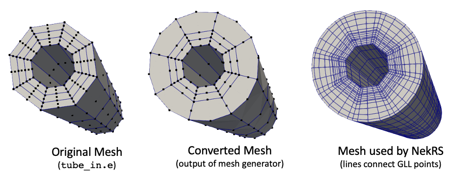
Figure 1: Input, output, and NekRS meshes involved in mesh conversion example
For a second example, consider the case where you have one boundary that you want to move with multiple origins. In this case, list the points in origins for each boundary, with a semicolon separating the origins to be used for each boundary.
[Mesh<<<{"href": "../../syntax/Mesh/index.html"}>>>]
  [fluid]
    type = FileMeshGenerator<<<{"description": "Read a mesh from a file.", "href": "FileMeshGenerator.html"}>>>
    file<<<{"description": "The filename to read."}>>> = fluid.exo
  []
  [to_hex20]
    type = NekMeshGenerator<<<{"description": "Converts MOOSE meshes to element types needed for Nek (Quad8 or Hex20), while optionally preserving curved edges (which were faceted) in the original mesh.", "href": "NekMeshGenerator.html"}>>>
    input<<<{"description": "The mesh we want to modify"}>>> = fluid
    boundary<<<{"description": "Boundary(s) to enforce the curved surface"}>>> = '1'
    radius<<<{"description": "Radius(es) of the surfaces"}>>> = '${fparse 7.646e-3 / 2.0}'
    origins<<<{"description": "Origin(s) about which to form the curved surfaces; if not specified, all values default to (0, 0, 0)"}>>> = '+0.00000000 +0.00000000 +0.00000000
               +0.00000000 +0.00896570 +0.00000000
               -0.00776452 +0.00448285 +0.00000000
               -0.00776452 -0.00448285 +0.00000000
               +0.00000000 -0.00896570 +0.00000000
               +0.00776452 -0.00448285 +0.00000000
               +0.00776452 +0.00448285 +0.00000000'
    geometry_type<<<{"description": "Geometry type to use for moving boundary nodes"}>>> = cylinder
  []

  parallel_type = replicated
[]Figure 2 shows the meshes involved in this second example; the original mesh (fluid.exo) is a HEX27 mesh, which gets converted to a HEX20 mesh where boundary 1 is moved according to the nearest origin from a set of 7 different origins. This allows you to group all the surfaces into one sideset, but move them to unique origins.
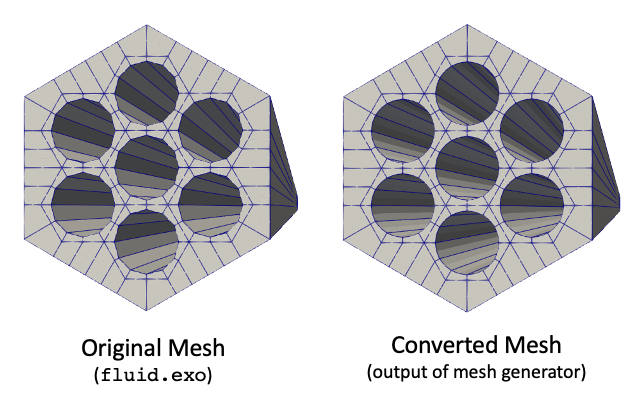
Figure 2: Input and output meshes when using multiple origins for a single sideset
When your mesh has boundary layers that are thin relative to the mesh movement needed to fit to cylinder surfaces, it is possible to obtain inverted elements. You can move the elements on the "other" side of the element face lying on the cylinder by setting the layers variable. With this parameter, if node on face 0 moves by to get onto the cylinder surface, then the same displacement is applied to that node's "pair" on the opposite face. An example of this usage is shown below, where nodes not on the boundary of interest are still moved in order to better mesh the boundary layer. Figure 3 shows the effect of setting layers (which defaults to zero) to 1.
[Mesh<<<{"href": "../../syntax/Mesh/index.html"}>>>]
  [fluid]
    type = FileMeshGenerator<<<{"description": "Read a mesh from a file.", "href": "FileMeshGenerator.html"}>>>
    file<<<{"description": "The filename to read."}>>> = fluid_with_bl.exo
  []
  [to_hex20]
    type = NekMeshGenerator<<<{"description": "Converts MOOSE meshes to element types needed for Nek (Quad8 or Hex20), while optionally preserving curved edges (which were faceted) in the original mesh.", "href": "NekMeshGenerator.html"}>>>
    input<<<{"description": "The mesh we want to modify"}>>> = fluid
    boundary<<<{"description": "Boundary(s) to enforce the curved surface"}>>> = '1'
    radius<<<{"description": "Radius(es) of the surfaces"}>>> = '${fparse 7.646e-3 / 2.0}'
    origins<<<{"description": "Origin(s) about which to form the curved surfaces; if not specified, all values default to (0, 0, 0)"}>>> = '+0.00000000 +0.00000000 +0.00000000
               +0.00000000 +0.00896570 +0.00000000
               -0.00776452 +0.00448285 +0.00000000
               -0.00776452 -0.00448285 +0.00000000
               +0.00000000 -0.00896570 +0.00000000
               +0.00776452 -0.00448285 +0.00000000
               +0.00776452 +0.00448285 +0.00000000'
    layers<<<{"description": "Number of layers to sweep for each boundary when forming the curved surfaces; if not specified, all values default to 0"}>>> = '1'
    geometry_type<<<{"description": "Geometry type to use for moving boundary nodes"}>>> = cylinder
  []

  parallel_type = replicated
[]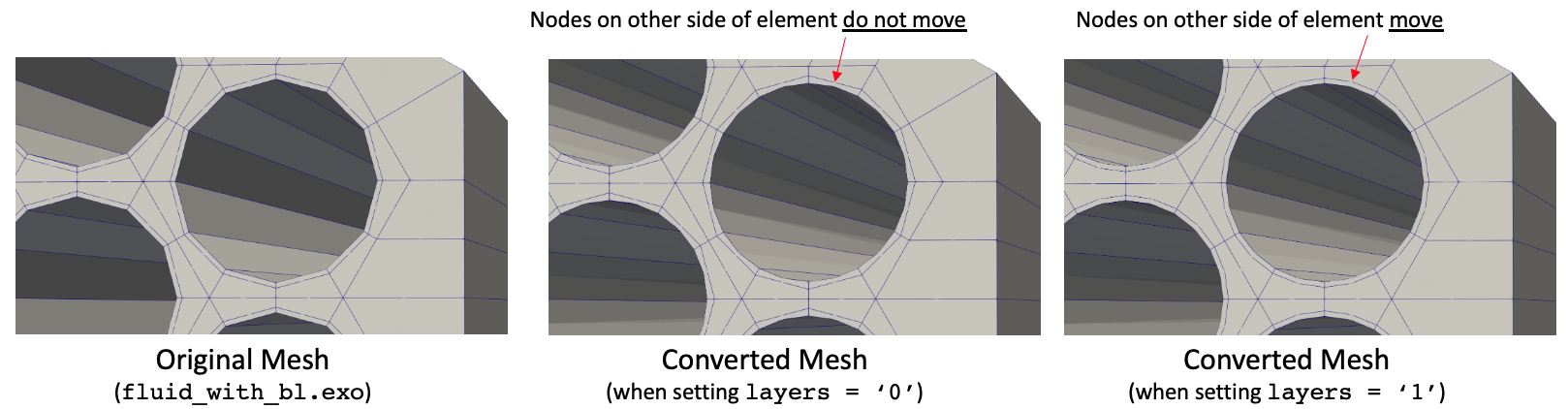
Figure 3: Input and output meshes when using different layers settings
You can also set the layers to be greater than 1, in which case multiple layers of boundary elements are moved. An example of this usage is shown below, where elements 3 layers deep are moved to match the cylinder surface. Figure 4 shows the effect of setting layers (which defaults to zero) to 3.
[Mesh<<<{"href": "../../syntax/Mesh/index.html"}>>>]
  [fluid]
    type = FileMeshGenerator<<<{"description": "Read a mesh from a file.", "href": "FileMeshGenerator.html"}>>>
    file<<<{"description": "The filename to read."}>>> = fluid_with_multiple_bl.exo
  []
  [to_hex20]
    type = NekMeshGenerator<<<{"description": "Converts MOOSE meshes to element types needed for Nek (Quad8 or Hex20), while optionally preserving curved edges (which were faceted) in the original mesh.", "href": "NekMeshGenerator.html"}>>>
    input<<<{"description": "The mesh we want to modify"}>>> = fluid
    boundary<<<{"description": "Boundary(s) to enforce the curved surface"}>>> = '1'
    radius<<<{"description": "Radius(es) of the surfaces"}>>> = '${fparse 7.646e-3 / 2.0}'
    origins<<<{"description": "Origin(s) about which to form the curved surfaces; if not specified, all values default to (0, 0, 0)"}>>> = '+0.00000000 +0.00000000 +0.00000000
               +0.00000000 +0.00896570 +0.00000000
               -0.00776452 +0.00448285 +0.00000000
               -0.00776452 -0.00448285 +0.00000000
               +0.00000000 -0.00896570 +0.00000000
               +0.00776452 -0.00448285 +0.00000000
               +0.00776452 +0.00448285 +0.00000000'
    layers<<<{"description": "Number of layers to sweep for each boundary when forming the curved surfaces; if not specified, all values default to 0"}>>> = '3'
    geometry_type<<<{"description": "Geometry type to use for moving boundary nodes"}>>> = cylinder
  []

  parallel_type = replicated
[]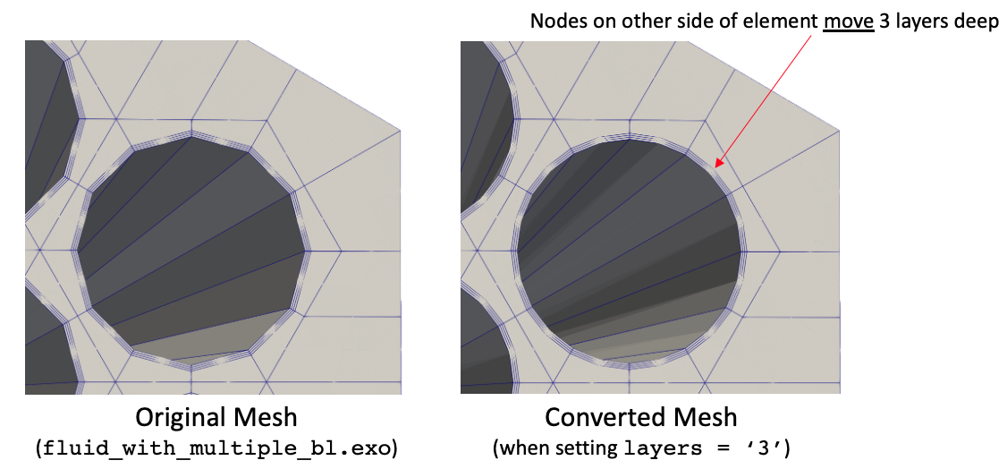
Figure 4: Input and output meshes when using layers = 3
Finally, you can move the corners of your mesh to a specified radius of curvature. In the example below, the original mesh has an outer boundary that matches a regular six-sided polygon. We move the corners, as well as attached boundary layers, to have a radius of curvature.
[Mesh<<<{"href": "../../syntax/Mesh/index.html"}>>>]
  [fluid]
    type = FileMeshGenerator<<<{"description": "Read a mesh from a file.", "href": "FileMeshGenerator.html"}>>>
    file<<<{"description": "The filename to read."}>>> = with_bl.exo
  []
  [rotate]
    type = TransformGenerator<<<{"description": "Applies a linear transform to the entire mesh.", "href": "TransformGenerator.html"}>>>
    input<<<{"description": "The mesh we want to modify"}>>> = fluid
    transform<<<{"description": "The type of transformation to perform (TRANSLATE, TRANSLATE_CENTER_ORIGIN, TRANSLATE_MIN_ORIGIN, ROTATE, SCALE, ROTATE_WITH_MATRIX, ROTATE_EXT)"}>>> = rotate
    vector_value<<<{"description": "The value to use for the transformation. When using TRANSLATE or SCALE, the xyz coordinates are applied in each direction respectively. When using ROTATE, the values are interpreted as the Euler angles phi, theta and psi given in degrees. For ROTATE_EXT, an extrinsic rotation is carried out using prescribed Euler angles alpha, beta, and gamma in degrees."}>>> = '30.0 0.0 0.0'
  []
  [to_hex20]
    type = NekMeshGenerator<<<{"description": "Converts MOOSE meshes to element types needed for Nek (Quad8 or Hex20), while optionally preserving curved edges (which were faceted) in the original mesh.", "href": "NekMeshGenerator.html"}>>>
    input<<<{"description": "The mesh we want to modify"}>>> = rotate
    boundaries_to_rebuild<<<{"description": "Boundary(s) to retain from the original mesh in the new mesh; if not specified, all original boundaries are kept."}>>> = '1 2 3 4'
    geometry_type<<<{"description": "Geometry type to use for moving boundary nodes"}>>> = cylinder

    curve_corners<<<{"description": "If 'geometry_type = cylinder', whether to move elements to respect radius of curvature of polygon corners"}>>> = true
    polygon_sides<<<{"description": "If 'geometry_type = cylinder' and when curving corners, the number of sides of the polygon to use for identifying corners"}>>> = 6
    polygon_size<<<{"description": "If 'geometry_type = cylinder' and when curving corners, the size of the polygon (measured as distance from center to a corner) to use for identifying corners"}>>> = 0.018001405522227287
    polygon_boundary<<<{"description": "If 'geometry_type = cylinder', boundary to enforce radius of curvature for polygon corners"}>>> = '4'
    polygon_layers<<<{"description": "If 'geometry_type = cylinder' and when curving corners, the number of layers to sweep for each polygon corner"}>>> = 3
    corner_radius<<<{"description": "If 'geometry_type = cylinder' and when curving corners, the radius of curvature of the corners"}>>> = 0.002
  []

  parallel_type = replicated
[]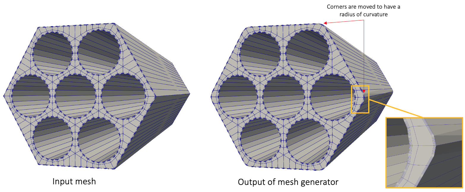
Figure 5: Input and output meshes when enforcing radius of curvature at polygon corners
Sphere Example
All examples in this section use geometry_type = sphere. For example, if you have a sphere of radius , you can move the nodes on the sphere surface to a new radius, say .
[Mesh<<<{"href": "../../syntax/Mesh/index.html"}>>>]
  [sphere]
    type = FileMeshGenerator<<<{"description": "Read a mesh from a file.", "href": "FileMeshGenerator.html"}>>>
    file<<<{"description": "The filename to read."}>>> = sphere_in.e
  []
  [move]
    type = NekMeshGenerator<<<{"description": "Converts MOOSE meshes to element types needed for Nek (Quad8 or Hex20), while optionally preserving curved edges (which were faceted) in the original mesh.", "href": "NekMeshGenerator.html"}>>>
    input<<<{"description": "The mesh we want to modify"}>>> = sphere
    geometry_type<<<{"description": "Geometry type to use for moving boundary nodes"}>>> = sphere
    radius<<<{"description": "Radius(es) of the surfaces"}>>> = 0.6
    boundary<<<{"description": "Boundary(s) to enforce the curved surface"}>>> = '0'
  []

  parallel_type = replicated
[]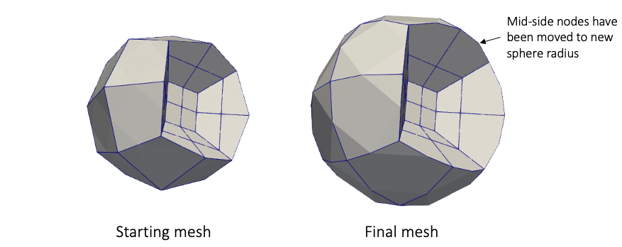
Figure 6: Input and output meshes when enforcing sphere radius
Input Parameters
- axiszIf 'geometry_type = cylinder', the axis of the mesh about which to build the cylinder surface(s)
Default:z
C++ Type:MooseEnum
Controllable:No
Description:If 'geometry_type = cylinder', the axis of the mesh about which to build the cylinder surface(s)
- boundaries_to_rebuildBoundary(s) to retain from the original mesh in the new mesh; if not specified, all original boundaries are kept.
C++ Type:std::vector<BoundaryName>
Controllable:No
Description:Boundary(s) to retain from the original mesh in the new mesh; if not specified, all original boundaries are kept.
- boundaryBoundary(s) to enforce the curved surface
C++ Type:std::vector<BoundaryName>
Controllable:No
Description:Boundary(s) to enforce the curved surface
- corner_radiusIf 'geometry_type = cylinder' and when curving corners, the radius of curvature of the corners
C++ Type:double
Unit:(no unit assumed)
Range:corner_radius >= 0.0
Controllable:No
Description:If 'geometry_type = cylinder' and when curving corners, the radius of curvature of the corners
- curve_cornersFalseIf 'geometry_type = cylinder', whether to move elements to respect radius of curvature of polygon corners
Default:False
C++ Type:bool
Controllable:No
Description:If 'geometry_type = cylinder', whether to move elements to respect radius of curvature of polygon corners
- geometry_typeGeometry type to use for moving boundary nodes
C++ Type:MooseEnum
Controllable:No
Description:Geometry type to use for moving boundary nodes
- layersNumber of layers to sweep for each boundary when forming the curved surfaces; if not specified, all values default to 0
C++ Type:std::vector<unsigned int>
Controllable:No
Description:Number of layers to sweep for each boundary when forming the curved surfaces; if not specified, all values default to 0
- originsOrigin(s) about which to form the curved surfaces; if not specified, all values default to (0, 0, 0)
C++ Type:std::vector<std::vector<double>>
Unit:(no unit assumed)
Controllable:No
Description:Origin(s) about which to form the curved surfaces; if not specified, all values default to (0, 0, 0)
- origins_filesOrigin(s) about which to form the curved surfaces, with a file of points provided for each boundary. If not specified, all values default to (0, 0, 0)
C++ Type:std::vector<std::string>
Controllable:No
Description:Origin(s) about which to form the curved surfaces, with a file of points provided for each boundary. If not specified, all values default to (0, 0, 0)
- polygon_boundaryIf 'geometry_type = cylinder', boundary to enforce radius of curvature for polygon corners
C++ Type:BoundaryName
Controllable:No
Description:If 'geometry_type = cylinder', boundary to enforce radius of curvature for polygon corners
- polygon_layer_smoothingIf 'geometry_type = cylinder' and when curving corners, the multiplicative factor to apply to each boundary layer; if not specified, all values default to 1.0
C++ Type:std::vector<double>
Unit:(no unit assumed)
Controllable:No
Description:If 'geometry_type = cylinder' and when curving corners, the multiplicative factor to apply to each boundary layer; if not specified, all values default to 1.0
- polygon_layers0If 'geometry_type = cylinder' and when curving corners, the number of layers to sweep for each polygon corner
Default:0
C++ Type:unsigned int
Controllable:No
Description:If 'geometry_type = cylinder' and when curving corners, the number of layers to sweep for each polygon corner
- polygon_originsIf 'geometry_type = cylinder', origin(s) about which to curve the polygon corners; if not specified, defaults to (0, 0, 0)
C++ Type:std::vector<std::vector<double>>
Unit:(no unit assumed)
Controllable:No
Description:If 'geometry_type = cylinder', origin(s) about which to curve the polygon corners; if not specified, defaults to (0, 0, 0)
- polygon_sidesIf 'geometry_type = cylinder' and when curving corners, the number of sides of the polygon to use for identifying corners
C++ Type:unsigned int
Range:polygon_sides > 2
Controllable:No
Description:If 'geometry_type = cylinder' and when curving corners, the number of sides of the polygon to use for identifying corners
- polygon_sizeIf 'geometry_type = cylinder' and when curving corners, the size of the polygon (measured as distance from center to a corner) to use for identifying corners
C++ Type:double
Unit:(no unit assumed)
Range:polygon_size > 0.0
Controllable:No
Description:If 'geometry_type = cylinder' and when curving corners, the size of the polygon (measured as distance from center to a corner) to use for identifying corners
- radiusRadius(es) of the surfaces
C++ Type:std::vector<double>
Unit:(no unit assumed)
Controllable:No
Description:Radius(es) of the surfaces
- retain_original_elem_typeFalseWhether to skip the conversion from QUAD9 to QUAD8, or from HEX27 to HEX20, to get into NekRS-compatible element type. This is primarily used to just allow MOOSE's AdvancedExtruderGenerator to extrude Quad9 elements.
Default:False
C++ Type:bool
Controllable:No
Description:Whether to skip the conversion from QUAD9 to QUAD8, or from HEX27 to HEX20, to get into NekRS-compatible element type. This is primarily used to just allow MOOSE's AdvancedExtruderGenerator to extrude Quad9 elements.
- rotation_angle0If 'geometry_type = cylinder' and when curving corners, the rotation angle (degrees) needed to apply to the original mesh to get a polygon boundary with one side horizontal
Default:0
C++ Type:double
Unit:(no unit assumed)
Controllable:No
Description:If 'geometry_type = cylinder' and when curving corners, the rotation angle (degrees) needed to apply to the original mesh to get a polygon boundary with one side horizontal
Optional Parameters
- enableTrueSet the enabled status of the MooseObject.
Default:True
C++ Type:bool
Controllable:No
Description:Set the enabled status of the MooseObject.
- save_with_nameKeep the mesh from this mesh generator in memory with the name specified
C++ Type:std::string
Controllable:No
Description:Keep the mesh from this mesh generator in memory with the name specified
Advanced Parameters
- nemesisFalseWhether or not to output the mesh file in the nemesisformat (only if output = true)
Default:False
C++ Type:bool
Controllable:No
Description:Whether or not to output the mesh file in the nemesisformat (only if output = true)
- outputFalseWhether or not to output the mesh file after generating the mesh
Default:False
C++ Type:bool
Controllable:No
Description:Whether or not to output the mesh file after generating the mesh
- show_infoFalseWhether or not to show mesh info after generating the mesh (bounding box, element types, sidesets, nodesets, subdomains, etc)
Default:False
C++ Type:bool
Controllable:No
Description:Whether or not to show mesh info after generating the mesh (bounding box, element types, sidesets, nodesets, subdomains, etc)
Debugging Parameters
Input Files
- (test/tests/meshgenerators/quad8_generator/convert_multiple_origin.i)
- (test/tests/meshgenerators/quad8_generator/convert_outer.i)
- (test/tests/meshgenerators/second_order_hex_generator/offcenter.i)
- (test/tests/meshgenerators/second_order_hex_generator/layers.i)
- (test/tests/meshgenerators/quad8_generator/multiple_origins.i)
- (test/tests/meshgenerators/second_order_hex_generator/multiple_origins.i)
- (test/tests/meshgenerators/quad8_generator/convert_some_sidesets.i)
- (test/tests/meshgenerators/second_order_hex_generator/repeated_sides.i)
- (test/tests/meshgenerators/quad8_generator/invalid_id.i)
- (test/tests/postprocessors/nek_yplus/pipe.i)
- (test/tests/meshgenerators/sphere/move.i)
- (test/tests/postprocessors/nek_pressure_surface_force/mesh.i)
- (test/tests/meshgenerators/polygon_corners/six_rotation.i)
- (test/tests/meshgenerators/second_order_hex_generator/invalid_elem.i)
- (test/tests/meshgenerators/second_order_hex_generator/three_layers.i)
- (test/tests/meshgenerators/second_order_hex_generator/convert.i)
- (test/tests/meshgenerators/second_order_hex_generator/convert_multiple_origin.i)
- (test/tests/meshgenerators/second_order_hex_generator/convert_multiple.i)
- (test/tests/meshgenerators/quad8_generator/convert_multiple.i)
- (test/tests/meshgenerators/second_order_hex_generator/multiple_sides.i)
- (utils/meshes/interassembly/convert.i)
- (test/tests/meshgenerators/second_order_hex_generator/convert_some_sidesets.i)
- (test/tests/meshgenerators/quad8_generator/convert.i)
- (test/tests/meshgenerators/quad8_generator/invalid_elem.i)
- (test/tests/meshgenerators/quad8_generator/convert_inner.i)
- (test/tests/meshgenerators/quad8_generator/offcenter.i)
- (test/tests/meshgenerators/polygon_corners/six_with_bl.i)
- (test/tests/meshgenerators/second_order_hex_generator/non_z.i)
- (test/tests/meshgenerators/quad8_generator/non_z.i)
- (utils/meshes/assembly/convert.i)
- (test/tests/meshgenerators/second_order_hex_generator/invalid_id.i)
- (utils/meshes/interassembly_w_structures/convert.i)
- (test/tests/meshgenerators/second_order_hex_generator/convert_outer.i)
- (test/tests/meshgenerators/quad8_generator/repeated_sides.i)
- (test/tests/meshgenerators/quad8_generator/multiple_sides.i)
- (tutorials/pincell_multiphysics/convert.i)
- (test/tests/meshgenerators/polygon_corners/six_translate.i)
- (tutorials/turbulence/pipe.i)
- (test/tests/meshgenerators/second_order_hex_generator/convert_inner.i)
- (test/tests/meshgenerators/polygon_corners/six.i)
- (test/tests/meshgenerators/polygon_corners/six_with_smoothing.i)
- (test/tests/meshgenerators/second_order_hex_generator/multiple_origins_files.i)
- (test/tests/meshgenerators/sphere/convert.i)
- (test/tests/meshgenerators/quad8_generator/convert_no_sidesets.i)
- (test/tests/meshgenerators/polygon_corners/corners_quad8.i)
- (test/tests/meshgenerators/second_order_hex_generator/convert_no_sidesets.i)